Skip to content
Greenhouse Projects

Seedling Propagation and Sapling Rooting Greenhouses: Engineering Design

Engineering design and specification for a seedling and sapling investment, resolving seedling production, sapling rooting, internal logistics and climate requirements within one integrated greenhouse system.

Engineering design and specification ready

AGIMEX role: Greenhouse project engineering, design and specification: AGIMEX prepared the integrated design and specification linking the structural requirements, climate control, boom irrigation, the subsurface drip and arrow dripper system of the rooting greenhouse, fertigation, root-zone management and automation of both greenhouses.

The project was designed as two separate greenhouses. The 4,752 m² seedling propagation greenhouse (9 spans × 9.6 m × 55 m) is designed with boom irrigation, tray logistics and climate zones; the separate 528 m² sapling rooting greenhouse (1 span × 9.6 m × 55 m) is designed with an irrigation system combining subsurface drip lines running through the rooting medium with arrow drippers. Structure, climate control, fertigation, root-zone management and automation were designed together for these two production types, and production and logistics interfaces were defined together with acceptance checks.

  • Production and logistics
  • Climate management
  • Irrigation and fertigation
  • Sapling rooting
Conceptual diagram; not a site layout or construction drawing.

Design and specification drawings

Design and specification drawingIsometric overview

Isometric schematic of the designed facility. A nine-span seedling propagation greenhouse with boom irrigation stands beside a separate single-span sapling rooting greenhouse irrigated by subsurface drip lines inside the rooting medium together with arrow drippers. The technical building stands between the two units. Frame count and spacing are representative.

Seedling propagation greenhouse — 9 spansSapling rooting greenhouseTechnical buildingBoom irrigationSubsurface drip + arrow drippers
Design and specification drawing (isometric, schematic): seedling propagation greenhouse, separate sapling rooting greenhouse and technical building. Frame count and spacing are representative; not to scale. Not an as-built record.
Design and specification drawingFacility layout

Plan of the designed facility. A nine-span seedling propagation greenhouse, eight spans for production and one for logistics, stands beside a separate single-span rooting greenhouse. Each span is 9.60 m wide and 55.00 m long; the production greenhouse is 86.40 m wide and the two units are 25.0 m apart. A central technical building serves both.

Width 86.40 mSeedling propagation greenhouse9 spans: 8 production + 1 logisticsSpan 9.60 mLength 55.00 m25.0 m separationSapling rooting greenhouse — 1 spanTechnical building

The position of the logistics span within the nine is schematic; the site arrangement is set in the site plan.

Design and specification drawing (redrawn): seedling propagation greenhouse and separate rooting greenhouse with a central technical building. Not an as-built record.
Design and specification drawingStructural engineering

Design cross-section: 9.60 m span, 5.00 m gutter height, 6.80 m ridge and 1.80 m roof rise. Columns, truss top and bottom chords and truss verticals and diagonals are distinct members. A mid-height bracing line provides lateral stability; its section is sized by structural calculation in the fabrication design. The longitudinal view shows wind bracing in the end and internal bays; bay spacing is set in the fabrication design from the wind and snow load calculation and the cover and screen systems. Foundation type, number and depth follow the geotechnical investigation and the uplift and compression calculation.

Cross-section — one span

Longitudinal view — bays and bracing

  • Span 9.60 m
  • Gutter height 5.00 m
  • Ridge 6.80 m
  • Roof rise 1.80 m
  1. Column: square hollow section, structural steel; section set by structural calculation for the wind, snow and crop load combinations
  2. Truss top and bottom chords: steel tube lattice arch; chord sections and truss depth sized by structural calculation for the span and load combinations
  3. Truss verticals and diagonals: steel tube lattice members connecting the chords; sections set by structural calculation
  4. Mid-height bracing line: for lateral stability and erection stiffness; section sized by structural calculation in the fabrication design
  5. Foundation and anchorage: type, number and depth set by the geotechnical investigation and the uplift and compression calculation

Double-layer PE film cover

Longitudinal wind bracing: steel tube bracing in end and internal bays; transfers longitudinal wind load to the foundations, sections set by structural calculation

Bay spacing: set in the fabrication design from the wind and snow load calculation and the cover and screen systems

Schematic; not to scale and not a site layout.

Design and specification drawing (redrawn from the technical proposal): single-span cross-section and longitudinal bracing of the steel frame. Sections are verified by project-specific structural calculation to EN 13031-1 and EN 1991-1-3/1-4; wind, snow and crop load assumptions are set for the site. Not an as-built record.
Design and specification drawingTechnical services zoning

Plan of a 12.00 by 6.00 m technical building with five zones: gas meter and regulator room behind a fire and gas separation wall, electrical and control room, boiler and heating equipment, water treatment and distribution, and a buffer tank for roof sprinklers. Natural gas, electricity and water enter from outside.

DCABE12.00 × 6.00 m — 72 m² footprint, clear height ≥ 3.50 mFire and gas separation wallNatural gasElectricityMains and borehole water
D — Gas meter / regulator room
≈3 m²
C — Electrical / control
≈7.5 m²
A — Boiler / heating equipment
≈30 m²
B — Water treatment and distribution
≈9 m²
E — Roof sprinkler buffer tank
≈12 m²

Zoning is a design constraint to be confirmed in the mechanical and electrical design against local regulations.

Design and specification drawing (redrawn): internal zoning of the central technical building. Not an as-built record.

Design and specification scope

Coordinated engineering design and technical specification. Fabrication drawings, site verifications and implementation documentation will be prepared in the next project phase.

Client identity, site location and identifying layout details are withheld for confidentiality.

Discuss a similar project

Explore our capabilities

Selected Project Studies

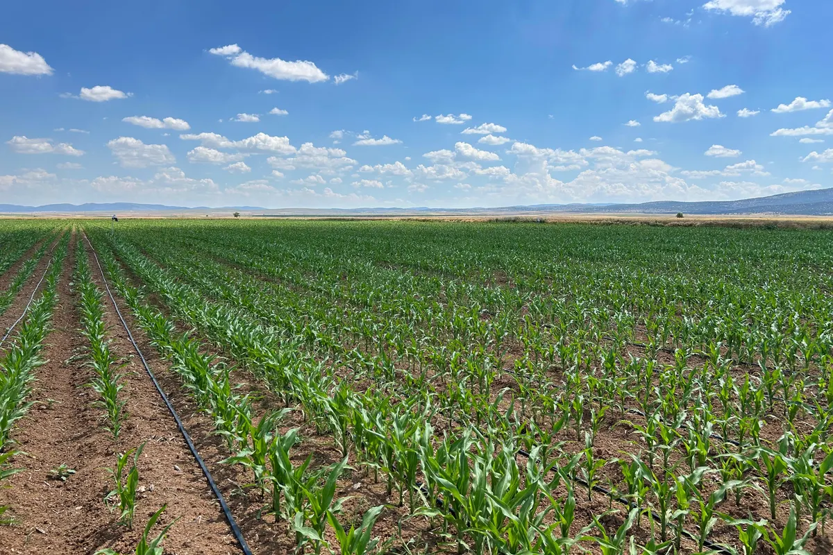
Rows of young maize with black drip lines running between them towards the horizon

Implemented and commissioned

Irrigation Projects & Water Management

Seed Maize Drip Irrigation, Fertigation and Automation

Seed maize · drip irrigation with fertigation · Türkiye · 2026

AGIMEX role: Design · Supply · Field implementation · Automation · Commissioning · Season monitoring

Drip irrigation with fertigation, block-level hydraulic distribution, field control, soil-moisture monitoring and season-long data evaluation.

View study →
Design drawing

Design completed

Irrigation Projects & Water Management

Irrigation Automation for a Large-Scale Orchard

Orchard · measurement-backed irrigation automation · Türkiye · 2026

AGIMEX role: Engineering & design

Block-level valve control, flow and water meter measurement, soil moisture monitoring in reference blocks, fertigation control, alert scenarios and irrigation reporting.

View study →
Design drawing

Design completed

Irrigation Projects & Water Management

Multi-Zone and Expandable Irrigation Infrastructure

Multi-zone, automated and expandable irrigation infrastructure · Türkiye · 2026

AGIMEX role: System architecture · Hydraulic design · Automation design

Irrigation and automation design with multiple water sources, zone control and room to expand, for orchard, vegetable, pasture and landscape areas.

View study →